CMOS cell이 회로 상에서 어떻게 존재하는 지 보자.
G1 NAND cell을 살펴보면 output에 fanout cell들(G2,G3,G4)을 drive하게 된다. 그리고 net(wire)에 wire cap이 Cs1,Cs2,Cs3,Cs4가 달려있다.
따라서 G1 cell의 output load cap은 Cout(G1) + Cin(G2) + Cin(G3) + Cin(G4) + Cs1 + Cs2 + Cs3 + Cs4

drive strength 크다 = resistance 작다 = size가 크다 = output high/low drive 크다
drive strength 작다 = resistance 크다 = size가 작다 = output high/low drive 작다
여기서 tr의 size는 width에 비례하고 r은 width에 반비례하므로 size가 클수록 r은 줄고 drive strength가 커지는 것이다.
drive strength는 driving할 수 있는 maximum cap을 결정한다.
maximum cap은 그 셀이 몇 개의 cell driving 할 수 있는지를 의미하는 Fanout을 결정한다.
즉, cell의 drive strength가 클수록 fanout이 많아 질 수 있다.

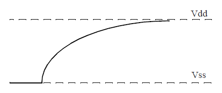
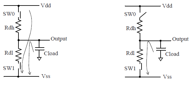
cell의 switching speed는 load cap에 의해 충전/방전하는 속도에 의해 결정된다.
따라서 output load cap과 resistance에 dependent하게 되는데 RC time constant(시상수)
rising time: V = Vdd * [1 - e -t/(Rdh * Cload)]
falling time: V = Vdd * e-t/(Rdl * Cload)


다음은 Propagation Delay에 대해서 알아보자
'VLSI > VLSI기초' 카테고리의 다른 글
| SPEF(Standard Parasitic Exchange Format) 기초 (0) | 2022.02.24 |
|---|---|
| lsf(Load Sharing Facility) (0) | 2020.08.11 |
| [VLSI기초 - CMOS logic] 2. Cell - Standard Cell (0) | 2020.05.25 |
| [VLSI기초 - CMOS logic] 1. CMOS logic basic (0) | 2020.05.25 |
| [VLSI기초 - CMOS logic] 0. MOSFET(NMOS, PMOS) (0) | 2020.05.25 |


댓글